M06 Loop Detection, part 1 - Ethernet, Spanning-Tree

Lecture Videos
on Loop Detection
Data networks have to have multiple redundant connections to achieve high-availability. One link failure does (and can)not distrupt traffic completely. Unfortunately the world is not perfect and these still happen from time to time.
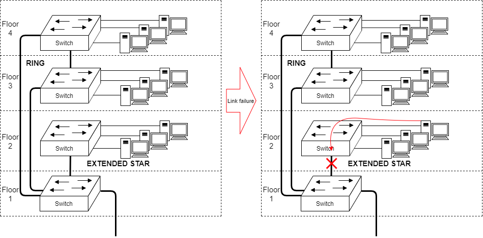
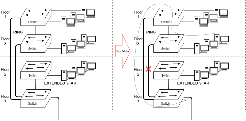
Examples of a link failure
(Extended) STAR topology recovery
As the trunk cable between Floor 1 and 2 doesn't have alternative links... the whole floor is disconnected.
RING topology recovery
As the trunk cable between Floor 1, 3 & 4 has a ring topology in place... one link doesn't kill the entire network.
In this chapter we discuss OSI Model Layer 2 - loop detection, in Ethernet.
Spanning Tree Protocol (STP) - IEEE 801.1D
Spanning Tree Protocol is one of the most dominant loop detection mechanisms in Ethernet Switch networks.
There is a lot of different versions of STP, such as MSTP, RSTP, PVSTP, ...
These are not of interest on the course. We just look at the basic STP and if you ever come across various versions of it. You will have to learn the details of that singular STP variation.
Info
There is competition, e.g. Ethernet Ring Protection Switching (ERPS), but STP still prevails as the basic loop detection mechanism (usually) taught in data networks.
Problem in the Ethernet Networks
Switches learn MAC addresses too well.
They spam out unknown MAC addresses out of all ports. Given a ring topology, this causes an infinite repetition loop.
Ethernet frames do not have an TTL -field!
Watch an example from the Safety Investigation Authority in Finland regarding HUS Healthcare district data network problems
The frames "never die out because they have been forwarded too often".
Lets look at this phenomenon via this powerpoint link (click the icon):

Same as an animation:
Solution, lets invent a protocol that detects loops in Ethernet networks! And so Spanning Tree Protocol was invented.
Bridge Protocol Data Unit - BPDU messages
In Spanning Tree Protocol, the Switches learn of each other through BPDU -messages.
When they learn of each other they elect a Root Bridge to act as the focal point of the switched network.
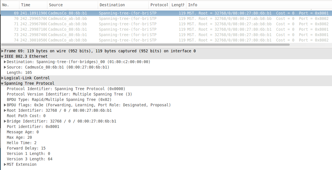
Example of a BPDU
Root Bridges
Root Bridge is the central point of the switched network. It has the lowest priority, thus is number 1 switch of the network.
The default priority is 32768 and it has to be increased or decreased with hops of 4096.
I would suggest the following values
4096 - on the root bridge
8192 - on the "backup" root bridge
32768 - on rest of the switches
Rest of the values are based on the design of spanning tree topology for a given network.
What if all the switches have the default value of 32768?
This is where Bridge ID comes in to play
Bridge ID is a singular identification for a switch. As they do not have IP addresses on Layer 2 of the OSI Model, the bridges use a "Base MAC" typically hardcoded into the switch. This is the MAC address used by communications from the switch (e.g. in management traffic). Lowest MAC address wins (HEX -> DEC).
In the previous BPDU example there are two MAC addresses in play
08:00:27:80:6b:b1 HEX -> 8 796 755 749 809 DEC (lower number)
08:00:27:ab:b8:bb HEX -> 8 796 758 587 579 DEC (higher number)
Thus 08:00:27:80:6b:b1 would be the Root Bridge if default priorities on both switches
Port States
In terms of receiving BPDUs, the ports go through the states below:
| State | Purpose |
|---|---|
| Disabled | Administratively down |
| Listening | Building "active" topology by receiving BPDUs |
| Learning | Building bridging table & receiving BPDUs |
| Forwarding | Sending / receiving user data |
| Blocking | Receives BPDUs only |
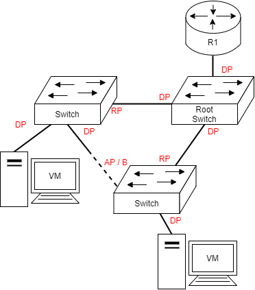
In terms of topology structure,
| State | Letter | Purpose |
|---|---|---|
| Designated Port | DP | Forwarding away from the root switch |
| Root Port | RP | Forwarding towards the root switch |
| Alternate Port | AP / B | Blocking for the Ethernet segment, but is an alternative path towards the root switch |
Given the topology below these would be as follows
Configuring STP
First we have to define on the switch VM's that we want to use STP on certain ports. Preferred way on this course is to add STP on all VLANs.
configure stpd s0 add vlan <name> ports all
On the selected root bridge only we drop the priority to be low
configure stpd s0 priority 4096
Then we turn on the protocol on the switch:
enable stpd s0
And then we can check the state of our switch by
show stpd s0
* EXOS-VM.1 # show stpd s0
Stpd: s0        Stp: ENABLED        Number of Ports: 2
Rapid Root Failover: Disabled
Operational Mode: MSTP          Default Binding Mode: 802.1D
MSTI Instance:  CIST
802.1Q Tag: (none)
Ports: 1,2
Participating Vlans: Default,servers,workstations
Auto-bind Vlans: Default
Bridge Priority            : 32768      Bridge Priority Mode: 802.1t
Operational Bridge Priority: 32768
BridgeID           : 80:00:08:00:27:80:6b:b1
Designated root        : 10:00:08:00:27:ab:b8:bb
CIST Root          : 10:00:08:00:27:ab:b8:bb
CIST Regional Root     : 10:00:08:00:27:ab:b8:bb
External RootPathCost      : 0  Internal RootPathCost: 200000
Root Port   : 1
MaxAge      : 20s   HelloTime     : 2s  ForwardDelay     : 15s
CfgBrMaxAge : 20s   CfgBrHelloTime: 2s  CfgBrForwardDelay: 15s
RemainHopCount: 19  CfgMaxHopCount: 20
Topology Change Time           : 35s        Hold time        : 1s
Topology Change Detected       : FALSE      Topology Change  : FALSE
Number of Topology Changes     : 1
Time Since Last Topology Change: 7038s
Topology Change initiated locally on Port none
Topology Change last received on Port 1 from 08:00:27:ab:b8:bb
Backup Root               : Off     Backup Root Activated  : FALSE
Loop Protect Event Window : 180s        Loop Protect Threshold : 3
New Root Trap             : On      Topology Change Trap   : Off
Tx Hold Count             : 6
And port states can be inspected through
show stpd s0 ports
* EXOS-VM.33 # show stpd s0 ports
Port     Mode   State      Cost  Flags     Priority Port ID Designated Bridge
1      802.1D FORWARDING 200000 eRapam--I- 128      8001    10:00:08:00:27:ab:b8:bb
2      802.1D FORWARDING 200000 eDap-w--B- 128      8002    80:00:08:00:27:80:6b:b1

Total Ports: 2

 ------------------------- Flags: ----------------------------
1:                e=Enable, d=Disable
2: (Port role)    R=Root, D=Designated, A=Alternate, B=Backup, M=Master
3: (Config type)  b=broadcast, p=point-to-point, e=edge, a=auto
4: (Oper. type)   b=broadcast, p=point-to-point, e=edge
5:                p=proposing, a=agree
6: (partner mode) d = 802.1d, w = 802.1w, m = mstp
7:                i = edgeport inconsistency
8:                S = edgeport safe guard active
                  s = edgeport safe guard configured but inactive
8:                G = edgeport safe guard bpdu restrict active in 802.1w and mstp
                  g = edgeport safe guard bpdu restrict active in 802.1d
9:                B = Boundary, I = Internal
10:               r = restricted role, t = active role
The Flags for the port are imporant in the print out above. The same as an table:
| Port | Mode | State | Cost | Flags | Priority | Port ID | Designated Bridge |
|---|---|---|---|---|---|---|---|
| 1 | 802.1D | FORWARDING | 200000 | eRapam--I- | 128 | 8001 | 80:00:08:00:27:ab:b8:bb |
| 2 | 802.1D | FORWARDING | 200000 | eDap-w--B- | 128 | 8002 | 80:00:08:00:27:80:6b:b1 |
Where row
- is the Root port and
- is the Designated port.
Continue to the Exercises

Self-reflect the material with a small quiz?
![]() Data Networks Quiz - M06 Loop Detection, part 1 - Ethernet, Spanning-Tree
Data Networks Quiz - M06 Loop Detection, part 1 - Ethernet, Spanning-Tree
Back to the Schedule?
License
This course and its materials are written by Karo Saharinen and licenced by Attribution-NonCommercial-NoDerivatives 4.0 International (CC BY-NC-ND 4.0) license.
